CFD Analysis of Flow Fields
around a Wing-Body Airplane Model with an Unstructured Grid Method
Fluid Mechanics Laboratory, Department of Aeronautics and Astronautics,
Introduction
Recently,
owing to a rapid development of computational performance and advancement of
analysis method, Computational Fluid Dynamics (CFD) makes a rapid progress. In
the aerospace field, CFD also plays an important role that is sometimes equal
to that in an experiment or a test flight. In our laboratory, several
researches have been conducted to establish advanced Reynolds Averaged Navie
Stokes (RANS) models and LES-RANS hybrid models and to improve their prediction
accuracy. So far, reasonable results have been achieved for flow fields around
a 2-D aerofoil or some 3-D models with simple shapes. However, it is still
difficult to apply these models to engineering
flow fields that consist of 3-D complex shapes.
The purpose
of this research is to assess a prediction accuracy of existing turbulence models
and to obtain valuable knowledge for
improving them, leading to the development of further advanced turbulence models applicable to
various complex engineering flow fields. As a part of this objective, the
present study aims to analyze flow fields around an
airplane model with an unstructured grid method.
Numerical
method and target of analysis
In
this study, all the calculations are performed
by the flow-simulation code ��FrontFlow/red [1]��, which is an open source program
developed in the project ��Revolutionary Simulation Software 21 (RSS21) [2]��. In
this study, large eddy simulation (LES) with the Smagorinsky model is adopted.
A discretization method is based on a node-centered finite volume method, and
the advection term is discretized by the 3rd�Corder upwind differential scheme.
In this study, Euler implicit method is used for the time integration.
DLR-F6
[3] model is selected as the present target of analysis. It was used in the 2nd
AIAA CFD Drag Prediction Workshop [3] in June 2003. In this study, a Wing-Body
(WB) model, which is a simpler configuration in the workshop, is chosen. The
Reynolds number is Re=![]() based on the mean aerodynamic code length and the inflow
velocity M=0.75. Figure 1 and Table 1 show the wind channel model and the wind
channel data, respectively.
based on the mean aerodynamic code length and the inflow
velocity M=0.75. Figure 1 and Table 1 show the wind channel model and the wind
channel data, respectively.
Table 1 Summary of
wind channel data.
|
Mach number |
0.75 |
|
Re (based on MAC) |
3.0��106 |
|
Reference temperature |
305K |
|
Mean aerodynamic chord |
141.2 mm |
|
Half model reference area |
72700.0 mm2 |
Grid system
and computational conditions
In this
study, prism cells are used near the airplane and far fields for the purpose of
resolving a boundary layer and avoiding rapid change of volume of cells. It is
noted that hexahedral cells are adopted in some particular regions near the
wing and the wing-body junction. Tetrahedral cells fill up rest
of the computational space. Figure 2 shows the computational grid used in this
study and Table 2 shows computational grid data. To reduce the number of grid
nodes, the model is cut in half and the symmetry boundary condition is specified at
the cut section (Fig. 3).
Table
2 Computational grid data.
|
Nodes |
927656 |
|
|
Elements |
Tetrahedral |
1338418 |
|
Hexahedral |
505746 |
|
|
Pyramid |
29342 |
|
|
Prism |
324590 |
|
|
Total |
2198096 |
|
Sample
Results
Representative
sample results are shown below. Figure 4 shows streamlines and color-contour
lines of Mach number. On the other hand, pressure (Cp) distributions around
airplane are illustrated in Fig. 5.
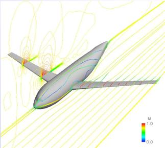
Fig. 4 Streamlines and
color-contour lines of Mach number.
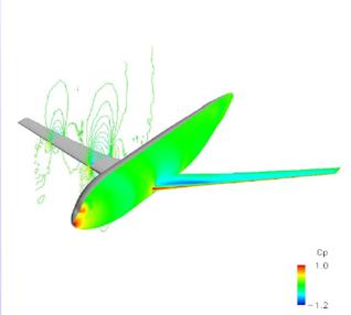
Fig. 5 Pressure (Cp)
distributions around airplane.
References
[1] Toshio Kobayashi: Numerical computation using
Advance/FrontFlow/red, Advance Soft
[2]
http://www.rss21.iis.u-tokyo.ac.jp/index.html
[3]
http://aaac.larc.nasa.gov/tsab/cfdlarc/aiaa-dpw/Workshop2/workshop2.html
All Rights Reserved,
Copyright(C) 2008, Fluid Mechanics Laboratory,
Department of Aeronautics
and Astronautics,